| Version 5 (modified by , 10 years ago) ( diff ) |
|---|
Index CRSs
This page describes how to use and interpret Index Coordinate Reference Systems (CRSs), and how they differs from other linear coordinate systems and especially how it differs from the internal grid CRS, known as CRS:1.
GML definitions for Index1D, Index2D and Index3D are already embedded in our [SecoreDevGuide SECORE] resolver and their official acknowledgment is on OGC table.
Definition
As you can verify by looking at the "extra" (non-EPSG) CRS definitions provided by SECORE, among others there are three new Index CRSs, namely 1D, 2D and 3D reference systems.
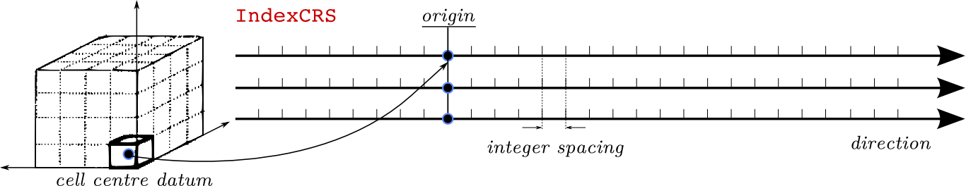
The index prefix refers to the fact that integral coordinates shall be used in the geometric (cartesian) space. The n-dimensional Coordinate System (CS) is supposed to be bound to an multidimensional array (marray) of cells: the origin of the CS is placed in the centre of the 0-cell. This represents the datum and completes the picture to define the CRS.

Using index CRSs can be useful especially when using rasdaman for applications not related to the geo-referenced world of satellite products, or more generally to remote-sensing imagery. For instance, rasdaman could be used to process large bio-medical images, which do not need a geo-reference.
The previous case is out of scope in the OGC services, and it is probably better handled via direct rasql requests (also via [PetascopeUserGuide Petascope] rasql web interface). However, more interestingly, index CRSs could also be used to access "pixel" coordinates from an image, or to access layers of height/time via their ordinal position in the stack (this requires CRS extensions [Features available]).
Index CRSs exploit indexed cartesian CSs by defining the Unit of Measure (Uom) of each of its axes to be an integral. The specific terminology that is used is GridSpacing, defined by OGC in the context of the deprecated (2D) Image CRS. Indeed index CRSs are considered the n-dimensional extension/generalization of the previously defined Image CRSs: this means replacing the typically-2D terminology of pixels, rows and columns with the more general cells and axis.
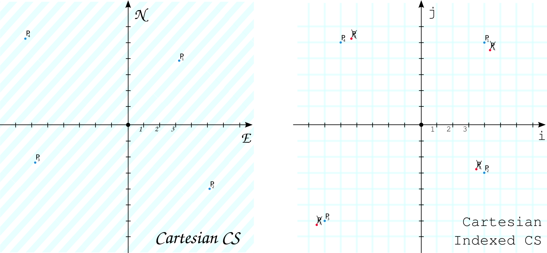
The following picture clarifies what is the space of coordinates covered by a standard 2D (linear) cartesian CS, and an indexed one:

The 2D space is fully covered on a geometric space with no additional constraints, whereas limiting the coordinates to integrals confines the address space to a grid of 0D points. While this is easily understandable, it has some important consequences: sample sizes (footprints) of coverages' points are confined to be 0D on an index CRSs since the areas between CRS points is not reachable and hence loses its meaning.
In the regular 2D case, usually a pixel represents its extent/area (though not always of course), while a coverage point is always a 0D point: on an index CRS the point is on integral coordinates, and the footprint would be half-pixel away from it, over unreachable spaces 0.5 GridSpacing away from it. Truncating this footprint to the legal index space, the footprints/pixels reduce to the point itself.
Grid origin and offset vectors
When assigning an index CRS as native reference system of a coverage, there are a few things that needs to be kept in mind: where to put the origin and which offset vectors (relative vectorial offsets) are needed. If you are not familiar with origin and offset vectors, please check this section.
rasdaman users are typically familiar with the CRS:1 keyword, which is a shortcut to tell the service that you are going to use internal marray (grid) coordinates in the subset:
for cov in ( <coverage_name> )
return encode(
  cov[ Long:"CRS:1"(0:100), Lat:"CRS:1"(0:200) ]
, "csv")
The internal CRS:1 space needs not be confused with Index CRSs (although there are ways to make them coincide): an important premise is that rasdaman, along with many other common GIS policies, puts origin in the upper-left corner of an image. This means in practice that picking the first row of an image (slice 0 on the northings axis) will return the top row, and increasing internal coordinates will yield negative steps in the geo-CRS.
The internal representation of a grid is represented by an origin (usually in [0:__:0:__:0]) and unit integral spacing. When using index CRSs, in order to correctly visualize an image, you must take care to properly set the offset vectors.

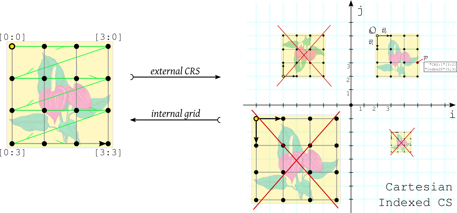
Lookig at the picture above, you can see correct and faulty ways of defining the external index representation of a grid (2D case):
I quadrant (+/+): origin is upperleft corner,i-vector is the positivei-versor[1,0]while thej-vector points down ([0,-1]) so that inverse proportionality on the second grid axis between internal and external representation is correctly maintained.II quadrant (-/+):j-vector is set as[0,1]and as a consequence the origin becomes the lower-left corner of the image: as a result we will see the image upside-down.III quadrant (-/-): origin is correctly set in the upper-left corner, but offset vectors have norm greater than one: while this is a technically viable solution, it also means that we lose the pixel-index correspondence: one internal index step equals a jump of 2 indexes in the external representation.IV quadrant (+/-): similarly, it does not make much sense to define vectors with norm less than one: moreover this solution would even prevent from slicing those point which do not lie over a legal area of the index CRS (at fractional positions).
This example is aimed at underlining the difference between the CRS:1 internal grid representation and the set of index CRSs. Albeit they are different concepts, they can also coincide in case i) the i/j coordinates of the origin equal the internal indexes of the grid (which is usually but not necessarily in [0:0:__:0]), ii) the offset vectors are the versors of the nD cartesian CS.
For some hands-on RasQL/WC*S query, our test datasets are actively using index CRSs: mr and rgb are 2D images, whereas irr_cube_1 is a fictitious toy 3D cube (with irregular spacing on the third k dimension) which purposely synchronizes its internal and external representation. See [RasdamanTestSuites this] page for more information.
Change label of the axes
TBD Parametrized
Attachments (3)
-
IndexVsCartesianCRS.png
(227.4 KB
) - added by 10 years ago.
index Vs linear CS
-
indexCrs.png
(44.3 KB
) - added by 10 years ago.
What is an index CRS.
-
IndexAndGrids.png
(272.0 KB
) - added by 10 years ago.
How to place grid on an index CRS.
Download all attachments as: .zip